Buildings and roofs
- Choosing a design mode
- Introduction to 3D design mode
- Irregular Buildings in 3D design mode
- Introduction to Quick Roof design mode
Choosing a design mode
When you first create a project you will get the choice of the which design mode you would like to use. The design mode affects how you model the roofs you plan to put panels on.
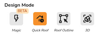
In Easy PV there are four options:
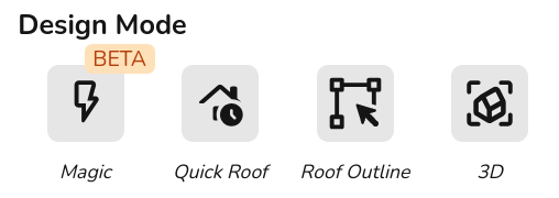
3D
- Create 3D property model by designing the roof from a satellite image and dimensions.
- Model obstructions and nearby buildings or trees that may cast shade on the roofs you're working on to get automatic shade analysis and improve the accuracy of the performance calculations.
- Automatically calculate scaffolding costs if using automatic pricing calculator.
For more info:
Magic BETA
- Create an automatic 3D design - works out the height and pitch of buildings and identifies any obstructions.
- Three free magic designs per day for standard users and unlimited for pro.
Roof outline
- Create roof model by outlining the roof from a satellite image and adjust the dimensions in the roofs task.
- 2D model so requires manual sunpath diagrams.
Quick Roof
- Create 2D roof using dimensions, pitch, orientation and tile type, can also spec ground mount systems.
- Does not use satellite imagery so a good option if the satellite imagery isn't usable.
For more info: Intro to Quick Roof.
Demo
Watch the same property be designed in each design mode:
Introduction to 3D design mode
3D design mode allows you to take into account nearby buildings or trees that may cast shade on the roofs you're working on. Easy PV can then complete and automatic shade analysis which saves you time and leads to more accurate projections for your customer.
Starting a 3D project
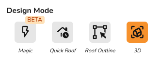
When creating your project, select the "3D" option.
Since 3D mode relies on the satellite map, you must then set the map either by zooming into the right location and selecting set from map or inputting the address and clicking set from address.
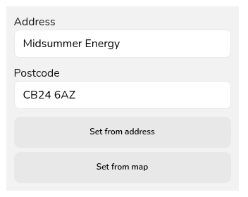
You can then click create and start your 3D design.
Examples
- Quick demo of a 3D design.
- Walk-through examples using the irregular building tool.
- Join our dedicated 3D design training session for more live examples.
Overview of 3D design
There are three views you can use to complete your design in 3D:
- Plan: This is a top down satellite view of the property.
- Drag and drop buildings and obstructions from the left-side menu and align with the satellite map.
- Click in the corners to view and edit dimensions.
Note that all dimensions in the plan view are all top-down. Use elevations view for pitched dimensions.
- Where available this will load with a property boundary. Only roofs within this boundary will be usable in the project.
- 3D: 3D view of the model.
- Useful to check elevations are correct.
- Expand 3D view to view full shading model.
- Elevations: View of heights and pitched dimensions.
- Click on a building, extension or obstruction in the plan view to display heights and pitched dimensions.
- Adjust dimensions by dragging or input directly by clicking on value.
Choosing satellite map: orthorectified and standard imagery
When designing atop the satellite map, you have two choices of which map data to use:
- Orthorectified: This uses geometrically corrected satellite data to give more accurate dimensions. This will not always be available
- Standard: This uses raw satellite data. Dimensions may be distorted, particularly for sloped structures.
If you are relying on the satellite map for dimensions, then orthorectified is the recommended option. We cannot guarantee the accuracy of the dimensions when using the standard imagery.
Selecting roofs to use
Once you have completed your design, click Next. A menu will then pop up showing the roofs.
- Easy PV will automatically select the roofs it thinks are most suitable based on the size, pitch and orientation.
- If a property boundary is included, only roofs within this property boundary will display - remove or edit the property boundary if roofs you modelled are missing.
- Select or de-select and roofs using the checkbox on the right.
- Place cursor over roofs to highlight them in the map on the left.
Once all the roofs you want to place panels on are selected, click Next in the bottom right to go to the panels task.
Automatic shade analysis
One of the key benefits of designing in 3D is Easy PV will calculate the shading on the panels automatically. In order to make the most out of this feature, it's therefore important to model any surrounding buildings or obstructions that would cast shade on the panels.
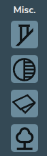
Drag and drop obstructions from the Misc. section, adjusting any heights in the elevations view:
Performance task
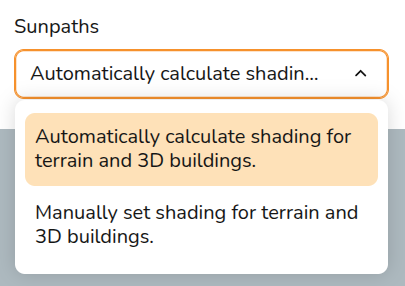
On all 3D projects, you will have the additional option in the performance task to automatically calculate sunpath diagrams:
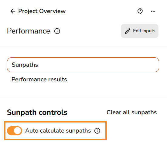
When this is selected, the shading factor/losses will be calculated for you. If you would like the shading to be calculated automatically each time, make sure this option is selected in your (pro) account performance settings:
Note that when using optimisers shading is not calculated per panel but per shading group. Read more about that here.
3D model
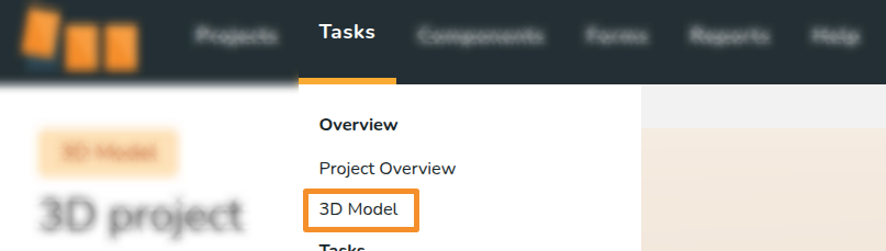
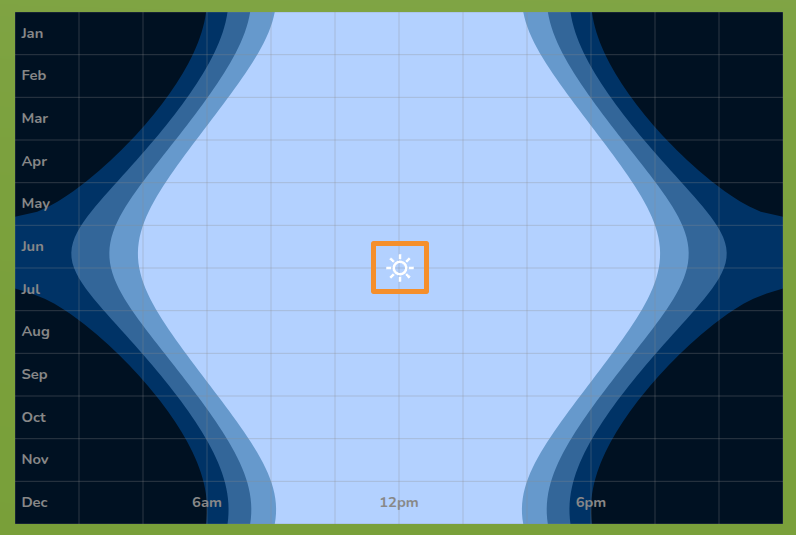
You can use the 3D model to check the shading on the roof. From the tasks drop-down, select 3D model:
In the top left you will see the date and time currently being modelled and a slider to adjust how quickly time passes.

If you click the pause icon, this diagram will appear in the bottom left. Drag the sun across the dates and times to see the shading at specific times.
Irregular Buildings in 3D design mode
The irregular building tool allows you to create unusual roof shapes that cannot be modelled using the standard roof options.
Using irregular building tool
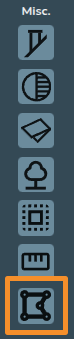
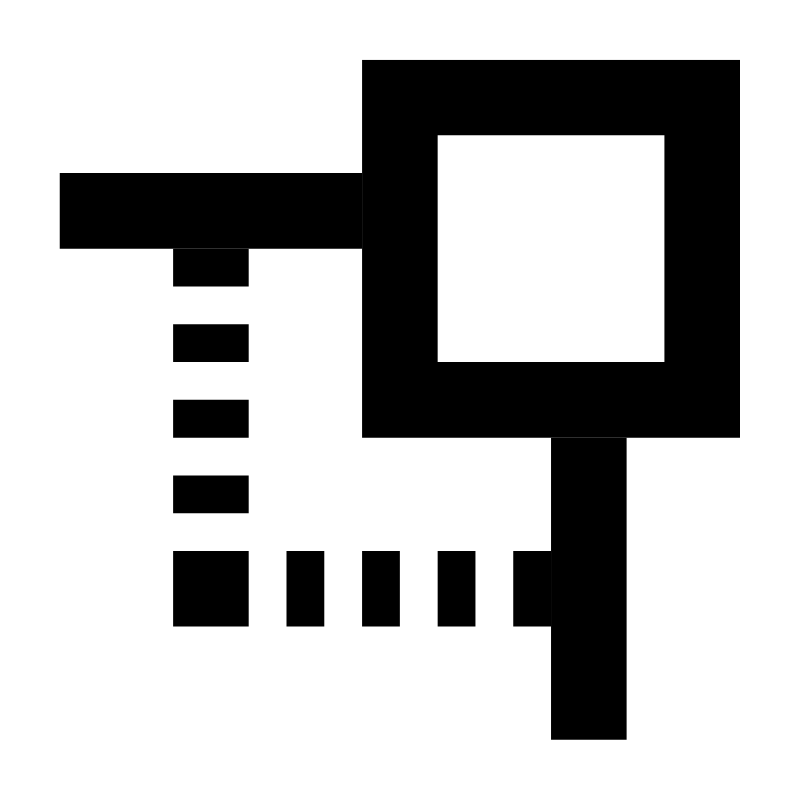
The irregular building tool can be found at the bottom of the Misc. section on the 3D left side-bar.
When creating a roof using the irregular building tool, there are a variety of additional handles you can use to accurately adjust the shape of the roof:
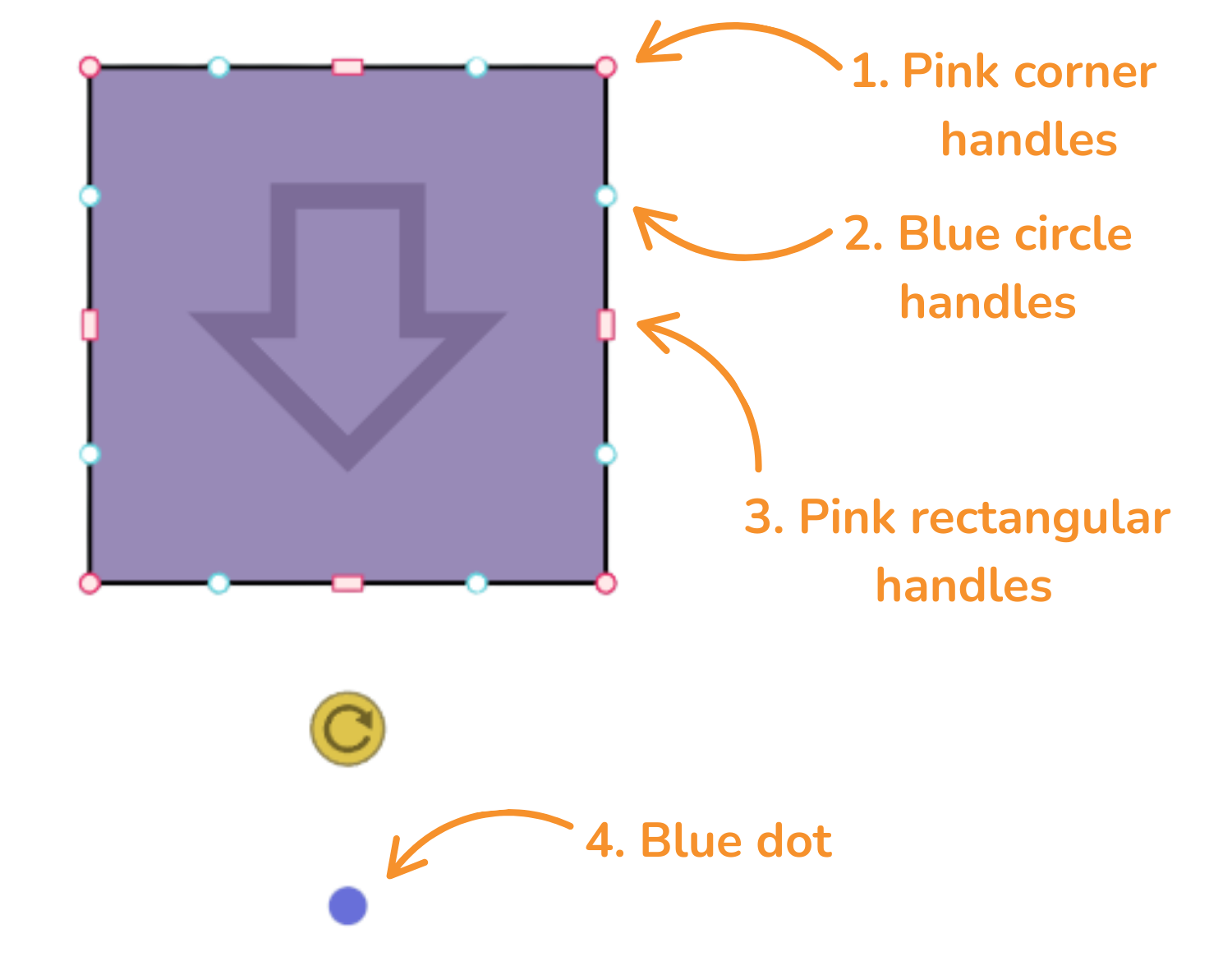
1. Pink corner handles
Click the pink corner handles to show dimensions of the associated roof sides. You can then click on the values to manually change these.
Click on the pink corner handles to use the following options:
 |
Square corner handle Use to resize the roof whilst keeping the adjacent sides at the same angle. |
|
|
Circle corner handle Use to move that point independently of the other points to create angled sides. This is the default option for the irregular building tool. |
|
|
Delete Delete the corner. This option is only available if there are 4 or more corners on a roof. |

See Example 1.
2. Blue circle handles
Click and drag the blue circle handles to allow you to split a side and create irregular shapes.
These will then convert to pink handles which you can delete if needed.
See Example 2.
3. Pink rectangular handles
Use the rectangular handle to resize the roof. Click on the pink rectangular handles to toggle between a square and curved cornered handles:
 |
Square cornered handle Use to extend a roof side out. |
 |
Curved cornered handle Use to extend the adjoining rood side independently of the others. This will create new corners and sides which can be deleted by clicking on the corners and then the bin icon. |
4. Blue dot
Drag the blue dot below the yellow rotation icon to indicate the direction that the panels will face. Whichever direction the arrow is facing is the panel and roof pitch direction.
See Example 1.
Examples
See below for some examples that demonstrate using the irregular building tool on actual roofs.
Example 1
Example 2
Introduction to Quick Roof design mode
With Easy PV's Quick Roof design mode you can model a roof without using satellite imagery, making it a good option if the satellite data isn't available. Simply model the roof using the dimensions, pitch and roof covering and add any obstructions.
Creating a Quick Roof design
Quick Roof is selected when you first create a project, input project details and under Design Mode select Quick Roof. Then click Create in the bottom right.
This will then take you to the Roof task where you can model the roof.
Roof task overview
In the Roof task you can create and edit your 2D roof model:
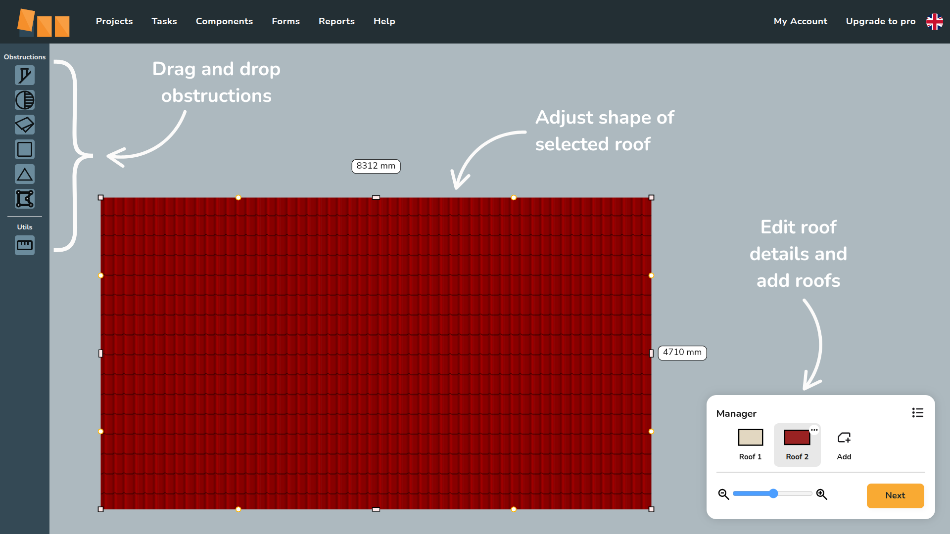
In the Roof Manager in the bottom right, clicking the three dots icon on the individual roofs will show the following options:
 |
Edit details Edit the roof type and dimensions. Changing the roof covering may affect the Panels task if the roof has panels on it and mounting selected. |
 |
Clone roof Copy the roof. This option will prompt you to input the name for the clone. |
 |
Delete Delete the roof from the project. This cannot be undone. |
Creating roof model
Initial roof details
When you first open a Quick Roof project, you will be prompted to fill in some initial roof details:
- Select the roof type and roof covering: this determines what mounting options are available to select.
- Input roof dimensions: width, height, pitch and orientation.
Orientation is taken in degrees from south going clockwise. Read more about setting the right orientation.
These details can be adjusted by clicking the three dots in the Roof Manager and selecting Edit. The dimensions can also be adjusted directly from the model by clicking on the corners and inputting the length.
Adjusting roof shape
When creating a roof in the Roof task, there are a variety of different handles you can use to accurately adjust the shape:
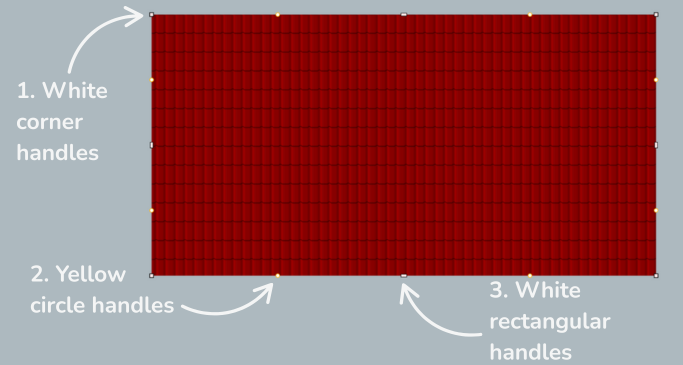
1. White corner handles
Click the white corner handles to show dimensions of the associated roof sides. You can then click on the values to manually change these.
Click on the white corner handles to switch between a square and circle handle:
- Use the square corner handles to resize the roof whilst keeping the adjacent sides at the same angle.
- Use the circle corner handles to move that point independently of the other points to create angled sides.
2. Yellow circle handles
Click and drag the yellow circle handles to allow you to split a roof edge and create irregular shapes. These will then convert to white handles which you can delete if needed.
Read more about the snapping guide (transparent rectangle) used here in the next section.
3. White rectangular handles
Click on the white rectangular handles to toggle between a square and curved cornered handles:
- Use the square cornered handle to extend the side of the roof.
- Use the curved cornered handle to extend the adjoining side independently of the others.
Adding obstructions
Once you have your overall roof shape, you can add obstructions. Including obstructions will help when planning where to place panels in the Panels task. Drag and drop any obstructions and use the snapping guide to ensure the obstruction positioning is correct.
 |
The snapping guide is a rectangle guide that you can set the dimensions of to help position obstructions correctly on a roof and to size your roof. Obstructions and roof sides will align with the sides and corners of the snapping guide. |
Here is an example of using the snapping guide to position a roof light. Use the same white handles described above to resize the snapping guide and obstructions.
If you are modelling an irregularly shaped obstruction, you can use the polygon obstruction. This uses the same white and yellow handles as the roof. You can also use the snapping guide to ensure the dimensions are correct when creating irregular shapes.