Panels, inverter and electrical
- How can I model an east-west panel layout?
- The mounting system I want to use isn't an option in the panels task, what can I do?
- I can’t allocate my panels to an inverter - all the options are red.
- The max voltage calculated in the inverter task doesn't match the Voc from the panel datasheet, why is this?
- How is DC cable sizing and voltage drop calculated?
How can I model an east-west panel layout?
To model an east-west panel layout, create a flat roof or ground mount area in any design mode.
In the panels task follow these steps:
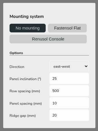
- Add panels to the roof/area and then select 'No mounting'
- Set the direction to east-west and configure the spacing as needed

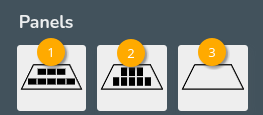
- Select option 1 to fill the roof/area with portrait panels, option 2 to fill the roof with landscape panels and 3 to clear the roof

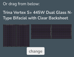
Or drag and drop portrait (right) or landscape (left) panels to build panel layout
This will not spec the mounting components but will mean the pitch and orientation of the panels is correctly modelled in performance calculations. Get in touch with Midsummer (UK) / (IE) for guidance on mounting components.
The mounting system I want to use isn't an option in the panels task, what can I do?
If the mounting system you'd like to use is not listed in the panels task, select No mounting. Then in the financial task, you can manually input your mounting system so it's still included in the quote.
If the mounting system you want to use is stocked by Midsummer (this includes Van der Valk and K2 flat), you can get in touch with your account handler for help with building the kit list.
I can’t allocate my panels to an inverter - all the options are red.
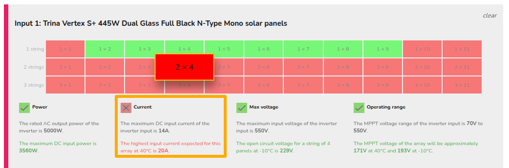
When all of the allocation options are red, Easy PV has determined the panel/inverter combination is not electrically viable. This means that the technical specifications of either the panels or the inverter are out of the range of the other.
When panels have been allocated to an input, Easy PV will outline any electrical issues in red text to make you aware of why it is not compatible. For a custom component this could mean one of the values you have input is incorrect
- Select the option you think should be possible with the inverter and panel
- See which option appears in red

- Check that value against the datasheet, it may be helpful to reference our component upload guide.
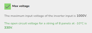
The max voltage calculated in the inverter task doesn't match the Voc from the panel datasheet, why is this?
The max voltage factors in both the open circuit voltage (Voc) and the temperature coefficient (ΔVoc/°C) of the panel. The value on the datasheet is measured at standard test conditions (STC) but the actual Voc of the panels will depend on the ambient temperature. As the temperature decreases, the Voc increases, so it is important to factor this into sizing the inverter.
In Easy PV, we do a calculation at -10°C, since the voltage increases at lower temperatures, the max voltage given in Easy PV will be higher than the number of panels multiplied by the open circuit voltage of the panels.
Example calculation
In the above case, the Voc is 37.45V and the temperature coefficient is -0.276%. This means for every increase in °C, the Voc decreases by 0.276%.
For standard test conditions (STC), the panel temperature is 25°C so the change in temperature to -10°C is 35°C, meaning we have
37.45 * (1 + (|-0.00276| * 35)) * 8 = 328.5 V
Easy PV does a slightly more conservative calculation:
37.45 * (1 - (-0.00276))35 * 8 = 329.94 V
where in each case 0.276% is divided by 100 to convert it 0.00276 per °C. This is then rounded to give 330V.
How is DC cable sizing and voltage drop calculated?
Easy PV returns the smallest cable cross-sectional area that achieves a voltage drop less than 1% of the voltage across the cable (or the largest cable if none do).
The voltage drop along a cable is the product of the current and resistance. The current is calculated in the inverter task and we calculate cable resistances from the IEC 60228/BS 6360 stranding chart.